Aircon blinking & malfunction code
(click to read more)
These error codes are provided based on the best of our knowledge, the same set of error codes may differ depending on different models. Check with your aircon manufacturer when in doubt:
When your “timer” light blinks, it is not that your timer is faulty. Most manufacturer uses blinking LED lights to indicate a
faulty air conditioning system
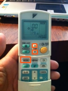
Video instructions to retrieve Daikin error code using
the remote controller:
1) If your DAIKIN remote controller comes with a
“test” button, use it. Otherwise press the
Temperature UP, Temperature DOWN and the
MODE buttons all at the same time.
2) You will see 00 on the remote controller. The
first “0” will be blinking.
Stand facing the particular air conditioner you
wanted to test.
Now press the Temperature UP button, “0” will
become “A” and the air conditioner will respond
with either a single beep or double beep.
Carry on pressing the Temperature UP button
and listen to the beeping sound, stop when you
hear a double beep.
For example: it is now showing “C0”.
Now press the MODE button, the second “0” will
be blinking.
Now press the Temperature UP button, “0” will
become “1” and the air conditioner will respond
with either a double beep or a continuous beep.
The continuous beep is the error code. For
example “C4”, it means it is a faulty liquid pipe
thermistor.
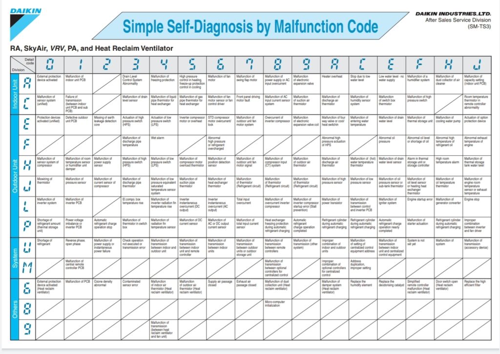
| DAIKIN error codes: |
| AO Indoor Error of external protection device A1 Indoor PCB defect A3 Indoor Malfunction of drain Level control system A5 Indoor Freeze-up prevention A6 Indoor Fan motor lock, Overload A7 Indoor Malfunction of swing motor flap A9 Indoor Malfunction of EEV AF Indoor Drain level above limit (clogging) AJ Indoor Malfunction of capacity set device C3 Indoor Malfunction of drain thermistor C4 Indoor Malfunction of liquid pipe thermistor C5 Indoor Malfunction of gas pipe thermistor C7 Indoor Lower louvre limit switch/motor C9 Indoor Malfunction of air thermistor CC Indoor Malfunction of moisture sensor CA Indoor Malfunction of discharge air thermistor CJ Indoor Malfunction of remote control thermistor CE Indoor Malfunction of radiant heat sensor E0 Outdoor Activation of outdoor safety device E1 Outdoor PCB defect E3 Outdoor Activation of high pressure switch E4 Outdoor Activation of low pressure switch E5 Outdoor Activation of compressor over heat protection E5 Outdoor Compressor motor lock E6 Outdoor Compressor start up error E6 Outdoor Standard compressor lock/over-current E7 Outdoor Fan motor lock, Overload E8 Outdoor Inverter input overcurrent E9 Outdoor Malfunction of EEV EA Outdoor Four way valve defective. F3 Outdoor Abnormal discharge pipe temperature F6 Outdoor Refrigerant overcharged FC Outdoor Low pressure drop. H3 Outdoor High pressure switch defect H4 Outdoor Low pressure switch defect H6 Outdoor Compressor motor position detection sensor error H7 Outdoor Fan motor position detection sensor error H8 Outdoor Current transformer error H9 Outdoor Malfunction of air thermistor J1 Outdoor Malfunction of pressure sensor J2 Outdoor Current sensor malfunction J3 Outdoor Malfunction of discharge pipe thermistor J4 Outdoor Low pressure saturation thermistor J5 Outdoor Malfunction of suction pipe thermistor J6 Outdoor Malfunction of heat exchanger thermistor J7 Outdoor Malfunction of heat exchanger liquid thermistor J8 Outdoor Malfunction of liquid pipe thermistor J9 Outdoor Malfunction of gas pipe thermistor JA Outdoor Malfunction of discharge pipe pressure sensor JC Outdoor Malfunction of suction pipe pressure sensor JH Outdoor Malfunction of oil temperature sensor L0 Outdoor Malfunction of inverter L3 Outdoor Electronic component box overheat L4 Outdoor Inverter cooling defect L5 Outdoor Comp motor ground fault, Short circuit L6 Outdoor Compressor motor grounding/short circuit L7 Outdoor Total input overcurrent L8 Outdoor Comp overload, Motor disconnected L9 Outdoor Compressor lock LA Outdoor Power unit malfunction LC Outdoor Transmission between inverter & outdoor P1 Outdoor Inverter over ripple P3 Outdoor Thermistor abnormality P4 Outdoor Power unit humidity sensor malfunction PJ Outdoor Failure of capacity set resistor U0 System Shortage of refrigerant or EEV failure U1 System Negative phase, Open phase U2 System Power supply insufficient U3 System Wiring check operation not executed U3 System Mismatch of indoor and outdoor units (Split only) U4 System Transmission error between indoor and outdoor PCB units U5 System Transmission to remote controller U6 System Malfunction transmission outdoor to BP unit U7 System Transmission between outdoor units U7 Outdoor Malfunction between outdoor boards(RMX/RX RK) U8 System Transmission between master & slave R/C U9 System Transmission error between indoor to outdoor UA System Excessive number of fancoils UC System Address duplication of central controllers UE System Transmission error between indoor & central UF System Refrigeration system not set/wiring – piping UH System Terminals 1 and 3 crossed (Split/Skyair) |
Daikin RA, Skyair, VRV, PA series malfunction Code
Mitsubishi (Mr Slim), non inverter error codes:
The Mr. Slim error code is represented by the number of blinks on the LED (light emitting diode).
| No of blinks | Fault |
| 1 | Indoor PCB (printed circuit board) |
| 2 | FCU thermistor faulty |
| 3 | FCU fan motor error |
| 4 | Compressor error (or starter) |
| 5 | Condenser thermistor |
| 6 | defrost thermistor |
| 7 | Condenser PCB error |
| 10 | Refrigerant error |
Mitsubishi (Starmex), Inverter error codes:
The Starmex error code is represented by the number of blinks on the LED (light emitting diode).
| No of blinks | Fault |
| 1 | Transmission error between inddor and outdoor board |
| 2 | FCU thermistor faulty |
| 3 | FCU fan motor error |
| 4 | Indoor pcb fault |
| 5 | Outdoor Power system fault (compressor or Inverter board) |
| 6 | Outdoor thermistor |
| 7 | Outdoor PCB error |
| 14 | Refer to SERVICE MANUAL |
Mitsubishi(Mr Slim), non inverter error codes:
The Mr. Slim error code is represented by the number of blinks on the LED (light emitting diode).
| No of blinks | Fault |
| 1 | Indoor PCB (printed circuit board) |
| 2 | FCU thermistor faulty |
| 3 | FCU fan motor error |
| 4 | Compressor error (or starter) |
| 5 | Condenser thermistor |
| 6 | defrost thermistor |
| 7 | Condenser PCB error |
| 10 | Refrigerant error |
Mitsubishi (Starmex), Inverter error codes:
The Starmex error code is represented by the number of blinks on the LED (light emitting diode).
| No of blinks | Fault |
| 1 | Transmission error between inddor and outdoor board |
| 2 | FCU thermistor faulty |
| 3 | FCU fan motor error |
| 4 | Indoor pcb fault |
| 5 | Outdoor Power system fault (compressor or Inverter board) |
| 6 | Outdoor thermistor |
| 7 | Outdoor PCB error |
| 14 | Refer to SERVICE MANUAL |
Samsung error codes:
The Samsung wall mounted air conditioner error code is represented by blinks on the different LEDs (light emitting diode):
* blinking
| Fault | Operation | Timer | Turbo |
| FCU Air Thermistor | * | * | |
| FCU coil thermistor | * | * | * |
| Indoor Fan motor | * | ||
| Indoor EEPROM (or options settings not set) | * | * | * |
| Outdoor Error | * | * |
LG error codes:
LG error code is a 2 digit error code (eg. 48), wired remote controller and some of the wall mounted aircon models provide a display to show this error codes. However, if the aircon/remote controller does not come with any displays, the error code will be a combination of the blinking LED as seen below. An error code of 48 will have the LEFT LED (2nd digit) blinking 8 times and the STAR LED (1st digit) blinking 4 times.

| Error Code | Fault |
| 01 | Indoor air thermistor error |
| 02 | Indoor coil thermistor error |
| 03 | indoor wired remote controller poor communication signal |
| 04 | Drain pump / Float switch activated (ceiling cassette unit) |
| 05 | Indoor / outdoor communication error |
| 06 | Outdoor pipe thermistor error |
| 07 | indoor/outdoor Different operation modes |
| CL | Child lock function selected, not an error, press timer and min button simultaneously for >3sec to toggle. |
| Po | Jet Cool mode selected, not a fault, press Jet cool to toggle |
| 21 | IPM fault (compressor over current) |
| 22 | CT2 (max current), current exceeded 14A |
| 23 | DC link low voltage, voltage less than 140V |
| 24 | Low / High pressure switch open |
| 25 | Abnormal AC voltage input |
| 26 | DC compressor position |
| 28 | DC link high voltage |
| 32 | Discharge pipe high temperature (inverter) |
| 33 | Discharge pipe high temperature (non-inverter) |
| 40 | CT circuit malfunction |
| 41 | Discharge pipe thermistor error |
| 44 | Air thermistor error |
| 45 | Condenser thermistor error |
| 46 | Suction pipe thermistor error |
| 47 | Discharge pipe thermistor error (non-inverter) |
| 48 | D-pipe and air sensor dual sensor unplugged |
| 51 | Over capacity |
| 52 | Communication error (main w sub) |
| 53 | Communication error (indoor w outdoor) |
| 54 | Outdoor 3-phase power supply error |
| 60 | EEPROM check sum mismatch |
| 61 | Condenser thermistor high temperature |
| 62 | Heat sink thermistor high temperature |
| 63 | Condenser thermistor low temperature |
| 65 | Heat sink sensor error |
| 67 | Outdoor BLDC Fan jammed / lock or fan circuitry problem |
| 105 | Communication error (main board w fan board) |
Hitachi (Ras-model) error codes:
The ras model error code is represented by the number of blinks on the LED (light emitting diode):
| No of Blinks | Fault |
| 14 | Jammed Fan Motor |
| 15 | Indoor Thermistor |
Sanyo (inverter, sap kmv series) error codes:
The above model error code is represented by the combination of blinks and lighted LED on the 3 different LED (light
emitting diode), operation, swing and timer.
* blinking
0 lighted up
| Fault | Operation | Swing | Timer |
| FCU Thermistor | * | ||
| Compressor Thermistor | * | ||
| Condenser Thermistor | * | * | |
| FCU coil thermistor | * | ||
| Condenser suction pipe thermistor | * | * | |
| Abnormal current | * | * | * |
| FCU miswire | 0 | ||
| High Ampere | 0 | ||
| Wrong Voltage | 0 | 0 | |
| IGBT protection activated (overheating) | 0 | 0 | |
| Outdoor ROM | 0 | 0 | |
| Compressor discharge gas overheat | 0 | 0 | |
| Indoor fan motor | 0 | 0 | 0 |
| 4 way valve switching problem | 0 | * | * |
| Condenser Fan motor | * | 0 | * |
| Compressor | 0 | * | 0 |
Fujitsu error codes (hard wired series)
When EE:EE is displayed, press “energy save” and “zone control” simultaneously for about 3-5 secs.
Or , press “temperature Up” and “temperature down” simultaneously for 3-5 secs.
Otherwise, try ‘Master ” and “Fan” simultaneously for 3-5 secs.
The lcd display should display the relevant error code.
| Code | Fault |
| E0 or 00 | Communication error – indoor to remote |
| E1 or 01 | Communication error – indoor to outdoor |
| E2 or 02 | Indoor Air Thermistor Open |
| E3 or 03 | Indoor Air Thermistor Shorted |
| E4 or 04 | Indoor Coil Thermistor Open |
| E5 or 05 | Indoor Coil Thermistor Shorted |
| E6 or 06 | Outdoor Coil Thermistor Open |
| E7 or 07 | Outdoor Coil Thermistor Shorted |
| E8 or 08 | Power source connection failure |
| E9 or 09 | Drain Problem (float switch activated) |
| EA or 0A | Outdoor Air Thermistor Open |
| EB or 0B | Outdoor Air thermistor Shorted |
| EC or 0C | Discharge Thermistor Open |
| ED or 0D | Discharge Thermistor Shorted |
| EE or 0E | High pressure problem |
| EF or 0F | Check refrigerant |
| 11 | Outdoor PCB error |
| 12 | Indoor fan motor error |
| 13 | Outdoor abnormal signal |
| 14 | Outdoor EEPROM failure |
| 15 | Compressor temperature failure |
| 16 | Pressure switch error |
| 17 | IPM failure |
| 18 | CT error |
| 19 | Active filter Module Failure |
| 1A | Compressor failure |
| 1B | Outdoor fan motor failure |
| 1C | Inverter to PCB comms failure |
| 1D | 2 way valve sensor error (heat pump series) |
| 1E | EEV error |
| 1F | Connection indoor unit error |
Fujitsu error codes (by reading at flashing LED from outdoor PCB)
Outdoor PCB Fault Codes
Inverter OD Unit PCBs (1 red LED)
OD PCB LED Pulses = 1
Models 9-30 = Comms Failure
Models 36-54 = Comms Failure
OD PCB LED Pulses = 2
Models 9-30 = Disch Sensor Fail
Models 36-54 = Disch Sensor Fail
OD PCB LED Pulses = 3
Models 9-30 = Pipe Sensor Fail
Models 36-54 = Pipe Sensor Fail
OD PCB LED Pulses = 4
Models 9-30 = Air Sensor Fail
Models 36-54 = Air Sensor Fail
OD PCB LED Pulses = 5
Models 9-30 = 2 Way Valve Sensor
Models 36-54 =
OD PCB LED Pulses = 6
Models 9-30 = 3 Way Valve Sensor
Models 36-54 =
OD PCB LED Pulses = 7
Models 9-30 = Compressor Thermistor
Models 36-54 = Compressor Thermistor
OD PCB LED Pulses = 8
Models 9-30 = Pressure Switch
Models 36-54 = Heat Sink Sensor Fail
OD PCB LED Pulses = 9
Models 9-30 = Indoor Comms Error
Models 36-54 = Pressure Switch
OD PCB LED Pulses = 10
Models 9-30 = Current Trip
Models 36-54 =
OD PCB LED Pulses = 11
Models 9-30 = CT Fail
Models 36-54 =
OD PCB LED Pulses = 12
Models 9-30 = Compressor Position Fail
Models 36-54 = IPM Error
OD PCB LED Pulses = 13
Models 9-30 = Compressor Start Fail
Models 36-54 = Compressor Position Fail
OD PCB LED Pulses = 14
Models 9-30 = Timer Failure
Models 36-54 = Compressor Start Fail
OD PCB LED Pulses = 15
Models 9-30 =
Models 36-54 = OD Upper Fan Fail
OD PCB LED Pulses = 16
Models 9-30 =
Models 36-54 = OD Lower Fan Fail
OD PCB LED Pulses = Slow Blink
Models 9-30 =
Models 36-54 = Protect Operation
Non Inverter OD PCBs (2 red LEDs)
LED1 = Blinks
LED2 = Blinks
OD PCB Fail
LED1 = 1 Pulse
LED2 = Lit
Power Source Failure
LED1 = 2 Pulse
LED2 = Lit
OD Disch Temp Sensor
LED1 = 3 Pulse
LED2 = Lit
OD Pipe Sensor
LED1 = 4 Pulse
LED2 = Lit
OD Air Sensor
LED1 = 5 Pulse
LED2 = Lit
Comms Failure
LED1 = 6 Pulse
LED2 = Lit
Indoor Unit Error
LED1 = 7 Pulse
LED2 = Lit
High Discharge Temp
LED1 = 8 Pulse
LED2 = Lit
High Pressure
LED1 = 9 Pulse
LED2 = Lit
Compressor Temp Abnormal
LED1 = 10 Pulse
LED2 = Lit
Compressor Temp Sensor Fail
Inverter Multi AOY30
This has 4 LEDs A,B, C & D to denote which circuit has the fault
Up to 8 flashes – faults are identical to above 9-30 Single System
9 Pressure Switch A
10 Pressure Switch B
11 Indoor Unit Indexing Problem
12 IPM Fail
13 Compressor Position Fail
14 Compressor Fail
15 OD Fan Upper Fail
16 OD Fan Lower Fail
17 PCB Fail
| Malfunction Code | Fault |
| H00 | No Fault Found |
| H11 | Communication error (indoor w outdoor) |
| H12 | Indoor unit capacity mismatch |
| H14 | Indoor air sensor (thermistor) error |
| H15 | Compressor thermistor error |
| H16 | Current Transformer (CT) open circuit |
| H19 | indoor fan motor jammed (locked) |
| H23 | indoor coil thermistor (1) error |
| H24 | indoor coil thermistor (2) error |
| H25 | Indoor e-ion abnormality |
| H27 | outdoor air thermistor error |
| H28 | Condenser coil thermistor error |
| H30 | Compressor thermistor error |
| H33 | Wiring connection error (indoor w outdoor) |
| H34 | Outdoor heat sink temperature abnormality |
| H36 | Outdoor gas pipe thermistor error |
| H38 | Indoor/outdoor mismatch (brand code) |
| H39 | Abnormal indoor operating / standby unit |
| H41 | Abnormal wiring or copper pipe connections |
| H50 | Condenser fan abnormality |
| H51 | Nozzle lock abnormality |
| H52 | Limit switch abnormality |
| H58 | Indoor gas sensor abnormality |
| H64 | Outdoor high pressure sensor abnormality |
| H97 | Condenser fan motor jammed (locked) |
| H98 | Indoor high pressure protection |
| H99 | Indoor anti freeze protection |
| F11 | Cooling / Heating cycle abnormality |
| F17 | Indoor standby unit freezing abnormality |
| F90 | Power factor correction (PFC) circuit protection x 2 |
| F91 | Refrigeration cycle abnormality |
| F93 | Compressor rotation failure |
| F94 | Compressor discharge pressure overshoot protection |
| F95 | High pressure protection (cool mode) |
| F96 | IPM (power transistor) overheating protection |
| F97 | Compressor overheating protection |
| F98 | Total running current protection |
| F99 | Outdoor Peak DC (direct current) protection |

Instruction to retrieve Panasonic error code
using the remote controller:
1) Turn off the aircon using the remote
controller.
2) Use a sharp object to press the “Check”
button. “00” will first appear.
3) Point the remote controller at the aircon
and press the “timer” up/down buttons to
toggle the error code.
4) once the correct error code is retrieved,
the aircon will beep.
Toshiba Malfunction Codes
| Code | Malfunction |
| 00 | No indoor units connected |
| 0C | Faulty indoor air thermistoir |
| 0D | Faulty indoor Coil Thermistor |
| 04 | Indoor – Outdoor communication error |
| 08 | Reverse change temperature |
| 09 | Protection device activated, no temperature change detected in fan coil. |
| 0B | Float switch activated |
| 12 | Indoor microprocessor fault |
| 14, 1C, 1D, 1F | Refer to outdoor unit (Super Multi) |
| 15 | Refer to Multi Controller |
| 18 | Outdoor El Thermistor error |
| 19 | Outdoor (liquid/Discharge) Thermistor error |
| 20 | Low pressure trip |
| 21 | High Pressure trip |
| 97 | LAN comm. fault, check indoor PCB |
| 98 | Duplicated zone address |
| 99 | No communication between inddor unit and its wired remote controller |
| 1E | High Compressor discharge temperature |
| B5 | External input display fault or high level refrigerant leak if RD1 is fitted. |
| B6 | External interlock display fault or high level refrigerant leak if RD1 is fitted. |
| B7 | Faulty slave unit (Group) |
| FF | No Fault |
TECO Fault Codes:
When a TECO air conditioner is faulty, the operation light will be flashing. The combination of the DEFROST, TIMER and AUTO will indicate
the type of malfunction. Please note that we’ve added our own interpretation on the last column.
| Defrost | Timer | Auto | Type of Fault | Our Interpretation |
| * | Module Protection | |||
| * | Compressor top protection against temperature | Compressor overheating or faulty discharge thermistor | ||
| * | Outdoor ambient sensor abnormal | Condenser air thermistor faulty | ||
| * | * | Too low or high voltage supply | Voltage supply error, check supply voltage | |
| * | * | * | Indoor ambient sensor abnormal | Indoor air thermistor faulty |
| * | * | Flash | Fan speed beyond control | Faulty fan motor |
| Flash | zero crossing examination error | |||
| Flash | * | Temperature fuse protection or Indoor / outdoor do not match | Condenser overheating, check fan speed and condenser heat exchanger or non matching indoor outdoor unit (check model and type) | |
| Flash | EEPROM data Error | EEPROM error | ||
| Flash | Flash | Flash | Indoor outdoor communication fault | Indoor / Outdoor PCB or cabling faulty |
| * | * | Indoor outdoor communication fault | Indoor / Outdoor PCB |
Midea Indoor Malfuction Codes (MSE /MSX/MSK Series)
| Code | Fault |
| E0 | EEPROM parameter error |
| E1 | Communication error – indoor to outdoor |
| E2 | Zero-crossing signal error |
| E3 | Fan speed out of control |
| E5 | Outdoor temperature Thermistor error |
| E6 | Indoor room/Coil Thermistor error |
| P0 | IGBT over -strong current protection |
| P1 | Over or low voltage protection |
| P2 | Temperature protection of compressor top |
| P4 | Inverter Compressor drive error |
Midea Outdoor Malfuction Codes ( 21K-24KBTU MSK Series)
| Code | Fault |
| 1 | Communication error – indoor to outdoor |
| 2 | Phase sequence error |
| 3 | Pressure protection |
| 4 | T3 Error |
| 5 | Indoor T1/T2 Error |
| 6 | Normal |